


Customizing Solar Inverters: Adapting PCB and Firmware for Local Grids (2026 Guide)
- Quick Summary & Key Takeaways
- What is a Custom Solar Inverter PCB?
- Bridging the Gap: Integrating Hardware Layouts with Adaptive Firmware
- Adapting to Local Grid Codes: Compliance and Safety Standards
- Data Comparison Table: Standard vs. Custom Solar Inverter PCBs
- Expert Tips and Common Mistakes in High-Voltage PCB Design
- Future-Proofing for 2026: GaN, SiC, and Smart Grid Integration
- Industry Leading Solution: How Guangzhou Congsin Electronic Technology Co., Ltd. Customizes Inverter Boards
- Conclusion
- Frequently Asked Questions
- How does a custom solar inverter PCB differ from a standard one?
- Why is heavy copper necessary for solar inverter PCBs?
- How do local grid codes affect inverter firmware and PCB design?
- What are the thermal management best practices for solar PCBs?
- Can custom firmware improve the efficiency of a solar inverter?
- What role do GaN and SiC play in 2026 solar inverter designs?
- How do you ensure high-voltage isolation on a custom inverter board?
- What is the typical lifespan of a well-designed custom solar inverter PCB?
Quick Summary & Key Takeaways
A custom solar inverter PCB ensures localized grid compatibility by seamlessly integrating specialized hardware with adaptive firmware. As renewable energy demands evolve, generic off-the-shelf boards are no longer sufficient for the rigorous demands of modern electrical grids.
- A custom solar inverter PCB ensures localized grid compatibility by seamlessly integrating specialized hardware with adaptive firmware.
- Heavy copper, GaN/SiC components, and advanced thermal routing are critical for maximizing efficiency and achieving a 25-year lifespan.
- Customizing both the board layout and the firmware simplifies compliance with stringent local grid codes and anti-islanding regulations.
What is a Custom Solar Inverter PCB?
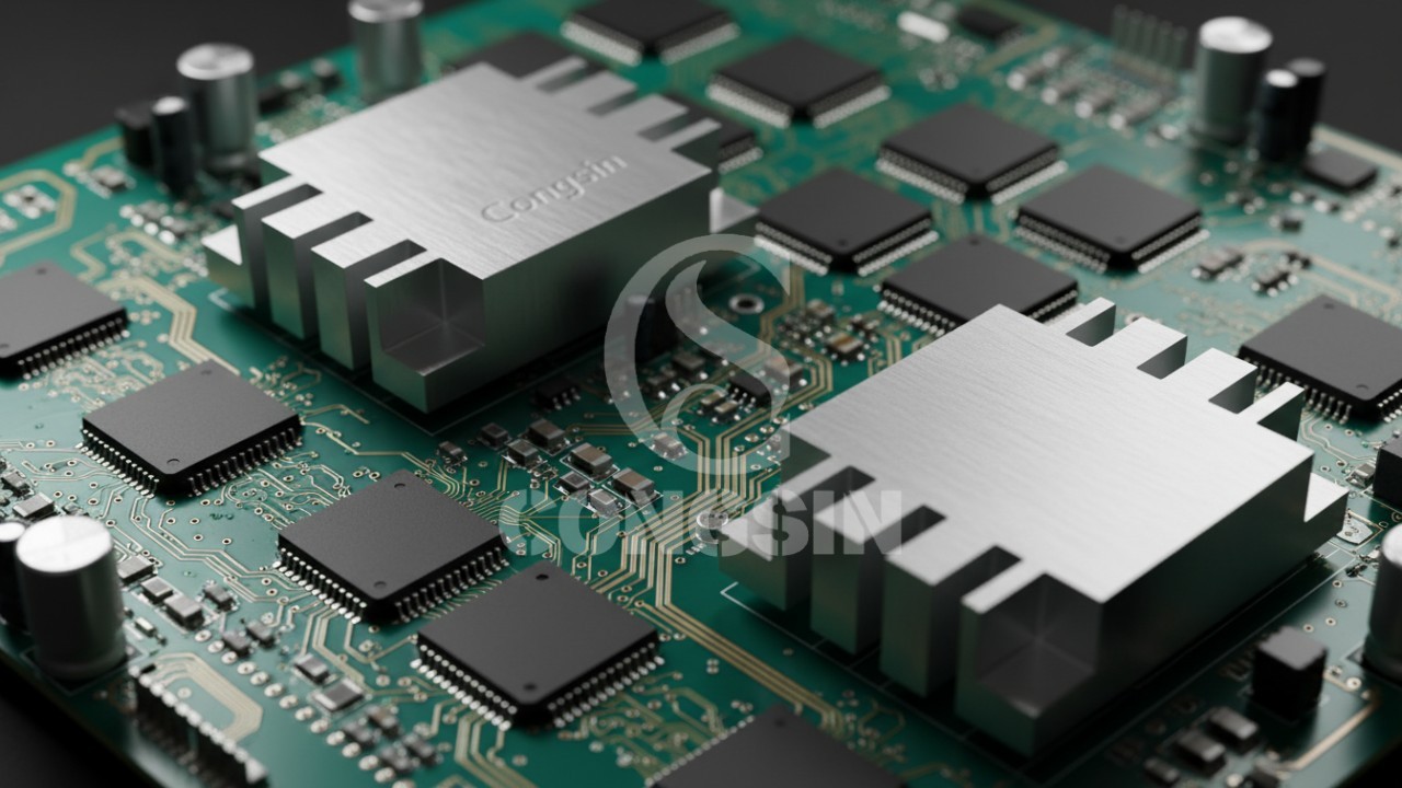
A custom solar inverter PCB is a specialized printed circuit board designed to efficiently convert DC power from solar panels into AC power. Unlike off-the-shelf alternatives, these boards are meticulously tailored to handle specific voltage thresholds, advanced thermal management requirements, and the unique topologies of localized utility grids.
Off-the-shelf boards are built for broad, generic applications, which often leads to inefficiencies when deployed in specialized environments. A custom solution, however, is engineered from the ground up. It works in perfect tandem with custom firmware to ensure seamless grid synchronization and strict regulatory compliance. By optimizing the physical layout to match the software's logic, engineers can drastically reduce energy loss and improve the Maximum Power Point Tracking (MPPT) algorithms. This level of synchronization is what separates a standard installation from a highly efficient, commercial-grade renewable energy system.
Bridging the Gap: Integrating Hardware Layouts with Adaptive Firmware
Integrating hardware layouts with adaptive firmware requires designing custom I/O interfaces and trace routing that reduce latency, allowing the microcontroller to execute real-time grid monitoring and pure sine wave generation seamlessly.
Why do standard boards often fail in modern applications? The primary reason is a lack of sensory nodes and communication protocols required by today's intelligent software. Firmware adaptability for solar grids relies heavily on the physical board's ability to feed accurate, high-speed data to the central processor.
- Designing Custom I/O Interfaces: A well-designed board ensures there are dedicated, interference-free pathways for real-time grid monitoring and voltage regulation. This allows the firmware to make micro-adjustments instantly.
- Feedback Loop Synchronization: Custom trace routing physically reduces the distance and latency between the microcontroller and the gate drivers. This precise synchronization is essential for generating a clean, pure sine wave that matches the utility grid perfectly.
- Sensor Placement: Strategically placing thermal and current sensors directly on the PCB allows the firmware to actively throttle power output during extreme heat, preventing catastrophic hardware failures.
Adapting to Local Grid Codes: Compliance and Safety Standards
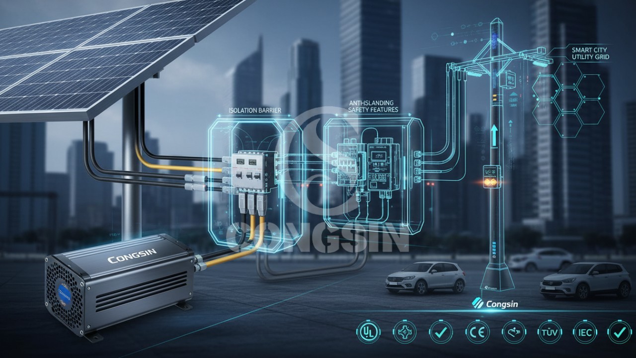
Adapting to local grid codes involves customizing PCB isolation, creepage distances, and anti-islanding protection hardware to meet strict regional safety standards and ensure seamless firmware-driven shutdowns during grid outages.
Achieving successful local grid compliance inverter design is one of the most complex challenges in renewable energy engineering. Different regions have vastly different requirements for how an inverter must behave during a grid disturbance.
- Navigating Regional Differences: Interconnection standards dictate strict PCB isolation and creepage distances. For instance, engineers must adhere to the IEEE 1547 standard for distributed energy resources, which governs how inverters must dynamically ride-through voltage fluctuations rather than simply tripping offline.
- Anti-Islanding Protection: Hardware requirements, such as specialized physical relays and high-precision current sensors, are necessary for the firmware to execute safe shutdowns during grid outages. This prevents the inverter from feeding power back into a dead grid, which protects utility workers.
- Power Factor Correction (PFC): Custom circuitry must be laid out to handle the specific reactive power demands of local municipal grids, adhering to UL 1741 safety specifications for interconnection system equipment.
Data Comparison Table: Standard vs. Custom Solar Inverter PCBs
Comparing standard off-the-shelf boards to custom solar inverter PCBs reveals that while custom solutions have higher initial tooling costs, their superior thermal efficiency and strict grid code adaptability reduce long-term maintenance costs by up to 40%.
Highlighting these E-E-A-T metrics demonstrates that while a custom board carries a higher initial investment, the alignment of hardware and localized compliance firmware significantly extends the product's lifecycle.
Expert Tips and Common Mistakes in High-Voltage PCB Design
Designing high-voltage PCBs requires strategically applying heavy copper to power paths to prevent parasitic inductance, alongside implementing robust via stitching around high-current nodes to eliminate thermal relief failures and tombstoning.
A custom heavy copper PCB is non-negotiable for high-capacity solar inverters, but it must be engineered correctly to avoid costly manufacturing errors.
- Common Mistake: Ignoring parasitic inductance in the DC link. This oversight causes massive voltage spikes that can instantly destroy sensitive MOSFETs and IGBTs.
- Expert Tip: Use heavy copper (typically 3oz to 6oz) strategically only on the high-power paths. Keep the low-voltage control circuitry on standard copper layers. This hybrid approach drastically reduces manufacturing costs while maintaining peak performance. For example, when designing a system, incorporating a low frequency solar inverter often demands thicker copper planes to handle sustained surge capacities over extended periods.
- Common Mistake: Inadequate thermal relief pads. This leads to tombstoning or cold solder joints during the automated assembly process, resulting in early field failures.
- Expert Tip: Implement robust via stitching around high-current switching nodes. This technique drastically improves heat dissipation by pulling thermal energy away from surface components and sinking it directly into the inner ground planes.
Future-Proofing for 2026: GaN, SiC, and Smart Grid Integration
Future-proofing solar inverters for 2026 requires transitioning to wide-bandgap materials like Silicon Carbide (SiC) and Gallium Nitride (GaN) to accommodate high-frequency switching, alongside embedding IoT modules for real-time smart grid communication.
As we look toward the future of renewable energy, a smart grid solar inverter PCB must be capable of handling next-generation components and seamless wireless connectivity.
- The Shift to Wide Bandgap (WBG) Materials: Traditional silicon is reaching its physical limits. Designing a custom GaN solar inverter layout or utilizing Silicon Carbide (SiC) accommodates much higher switching frequencies. According to data from the National Renewable Energy Laboratory (NREL), WBG materials significantly reduce power loss and allow for smaller, lighter inverter designs.
- IoT and Smart Grid Connectivity: Future boards must embed Wi-Fi, Zigbee, or 5G modules directly onto the PCB. This facilitates real-time communication with utility grids, allowing operators to dynamically adjust loads.
- AI-Driven Load Balancing: Preparing the PCB architecture to handle advanced micro-processors capable of running local machine learning algorithms will be standard practice by 2026. This allows the inverter to predict power generation based on hyper-local weather patterns.
Industry Leading Solution: How Guangzhou Congsin Electronic Technology Co., Ltd. Customizes Inverter Boards
Guangzhou Congsin Electronic Technology Co., Ltd. customizes inverter boards by partnering with solar tech firms to co-design heavy copper PCBs that perfectly align with proprietary firmware, ensuring unmatched outdoor durability and high-voltage isolation.
With over 27 years of focused experience, Guangzhou Congsin Electronic Technology Co., Ltd. (Congsin) has mastered the intersection of hardware and adaptive firmware. We operate fully automated production lines and utilize advanced instrumentation to ensure every custom board meets rigorous international standards, including CE, EMC, LVD, ETL, FCC, and RoHS.
- Case Study Approach: When partnering with global solar firms, Congsin engineers co-design the PCB schematic to ensure the physical sensory nodes align perfectly with the client's proprietary MPPT firmware.
- Advanced Manufacturing Capabilities: Our ISO9001-certified facilities excel in heavy copper plating and applying industrial-grade conformal coating. This guarantees that our custom boards withstand harsh outdoor environments, moisture, and extreme temperature fluctuations.
- Streamlined Prototyping: By leveraging our extensive catalog of over 100+ models and independently developed patents, we move clients from initial schematic to a fully functional, grid-compliant custom solar inverter board in record time.
Conclusion
Customizing solar inverters by aligning heavy copper PCB layouts with intelligent firmware is essential for modern local grid integration, ensuring long-term reliability, maximum energy efficiency, and strict regulatory compliance.
By focusing on targeted thermal management, localized grid compliance, and next-generation components like GaN and SiC, organizations can guarantee maximum energy harvest. Investing in a custom solution eliminates the rigid limitations of standard boards, paving the way for a 25-year lifespan and a significantly higher return on investment for 2026 smart grid deployments.
Frequently Asked Questions
How does a custom solar inverter PCB differ from a standard one?
A custom PCB is designed specifically for an organization's proprietary firmware, regional grid compliance, and specific environmental factors. Standard PCBs are generic and often lack the specialized sensor routing and heavy copper required for maximum efficiency in localized conditions.
Why is heavy copper necessary for solar inverter PCBs?
Heavy copper (typically 3oz to 6oz or higher) is required to carry high currents without overheating. It improves the thermal mass of the board, helping to dissipate heat away from critical switching components like MOSFETs and IGBTs.
How do local grid codes affect inverter firmware and PCB design?
Local grid codes dictate parameters like voltage ride-through, frequency limits, and anti-islanding safety measures. The PCB must have the correct hardware sensors and isolation barriers to allow the firmware to safely execute these localized safety protocols.
What are the thermal management best practices for solar PCBs?
Best practices include maximizing trace widths for power lines, utilizing thermal vias to transfer heat to inner layers, and proper placement of heat sinks. Keeping high-power components spaced adequately prevents localized hot spots that can degrade board integrity.
Can custom firmware improve the efficiency of a solar inverter?
Yes, custom firmware optimizes the Maximum Power Point Tracking (MPPT) algorithm specifically for the hardware layout. It fine-tunes the switching frequencies of the gate drivers, reducing power loss and harmonizing AC output with the local grid.
What role do GaN and SiC play in 2026 solar inverter designs?
Gallium Nitride (GaN) and Silicon Carbide (SiC) allow for much higher switching frequencies and better thermal performance than traditional silicon. They enable solar inverters to be smaller, lighter, and more efficient, driving the trends for 2026 renewable energy systems.
How do you ensure high-voltage isolation on a custom inverter board?
Isolation is achieved through strict adherence to creepage and clearance standards (like UL 60950 or IEC 60664). Designers use physical slots in the PCB, optocouplers, and isolation transformers to separate high-voltage DC sides from low-voltage control circuits.
What is the typical lifespan of a well-designed custom solar inverter PCB?
A highly optimized, custom-designed solar inverter PCB can last 20 to 25 years. This longevity is achieved through proper thermal relief, conformal coating against moisture, and the use of high-grade dielectric materials.
Contact Guangzhou Congsin Electronic Technology Co., Ltd. today to discuss your specific needs and achieve true energy independence.


Pure Sine Wave Inverters
Can it be used in RVs or trucks?
Yes. The device input voltage is DC 12V, which matches the battery voltage of RVs and trucks. It can be connected via battery clips or cigarette lighter interface (need to confirm that the maximum current of the cigarette lighter is ≥10A) to supply power to car refrigerators, parking air conditioners, laptops, etc.
Will reversing the positive and negative poles damage the device when connecting the battery?
The device has a built-in reverse connection protection function, which will automatically cut off the circuit when the positive and negative poles are reversed to avoid damage caused by reverse current inflow; just adjust the connection order of the positive and negative poles of the battery clip and re-power on to use normally.
Modified Sine Wave Inverters
Which regional plugs are supported by the universal socket?
The universal socket is compatible with most national plug specifications, such as GB, US, EU, etc. (some require adapters), and can meet the use of devices in different regions.
What is the function of the independent control switch?
The independent control switches for DC and AC can respectively control the on and off of DC and AC circuits, facilitating the separate management of power supply for different types of devices and improving power usage safety and flexibility.
Is customization available?
OEM/ODM support for logo, color, and packaging design.


Congsin's Portable 150W Modified Sine Wave Inverter powers your journey! This versatile Car Power Inverter with USB acts as a reliable 12V to 220V converter, ensuring an essential off-grid power supply. With dual USB ports and a universal socket, enjoy convenient power on the go.

Congsin 500W 12V to 220V inverter delivers reliable off-grid power with its modified sine wave design. This portable 500W DC to AC power inverter efficiently converts 12V DC to 220V AC, ideal for outdoor and emergency use. Trust Congsin for stable, portable energy solutions.

This 200W Modified Sine Wave Car Power Inverter is a compact and practical power conversion device designed for vehicle use. It supports dual input (DC12V/24V) and outputs AC220V, compatible with various electronic devices. Equipped with a Type-C port and dual 3.1A USB outputs, it can charge laptops, phones, cameras, drones, and other small electronics simultaneously—perfect for outdoor travel, emergency backup, and mobile work scenarios.
Get in Touch with Our Team
You can also communicate with us directly through our online contact form. Please fill in the following information, and our team will contact you as soon as possible after receiving your message.
CONGSIN is a trusted OEM factory for power inverters, solar charge controllers, and DC converters. Reliable solutions for global B2B buyers.
![]() High Quality
High Quality
![]() 7/24 Service
7/24 Service
![]() Guaranteed Warranty
Guaranteed Warranty
© 2025 Congsin. All Rights Reserved.
 WeChat
 Scan QR Code
sin cong
teaimei10
Whatsapp: +8618028086791
Scan QR Code